Leica MatrixScreener notes
The purpose of this page is to show how to collect data with the Leica SP5 HCS-A MatrixScreener Wizard.
- Before starting MatrixScreener
- Creating a new MatrixScreener experiment template
- Using an existing Matrix Screener template
Before starting MatrixScreener
Configuration
- Stage: Mark & Find: "Stack to focus position relation", choose "Symmetric" or "Asymmetric", depending on your experiment.
- IPS Masks: Uncheck "Additional z-Positions"
Start MatrixScreener in Leica AFS top menu.
See .
Check configurations (TODO screeenshots):
- The path where your data is exported.
- Your personal details.
- Your group details.
- "Setting (Page2)" -> " Autofocus Forecast Adjustment For Well": check "".
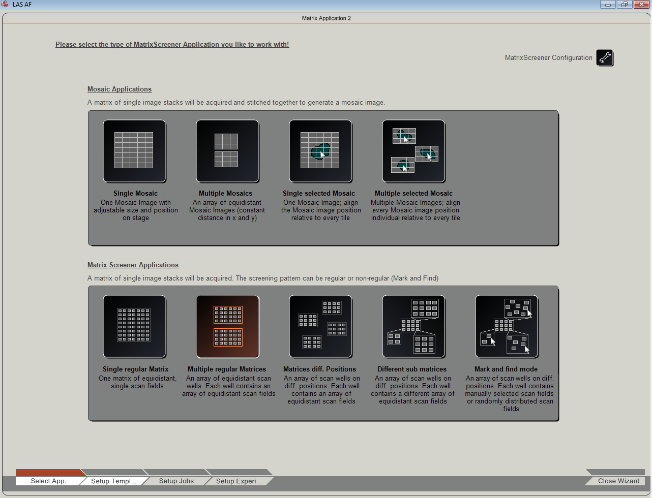
Creating a new MatrixScreener experiment template
"Setup Template" - describe the sample geometry
In this step you teach MatrixScreener where your samples are located.
- "In Select App.", click "".
- Click "Setup Templ...".
- Setting a field diameter on the view
- Set "Field Diameter" to 15, hit Enter. This is how big the fields are in the view. If you have few fields they can be bigger and if you have mo fields smaller are better.
- Set "Count of Field" to what you want to collect, for example 1 x 1 or 2 x 2.
Set "Count of Well" to match your plate and the objective.
The shape of the objective creates some limitations to how close to the edge of the plate it is possible to take images. In practice this means that with larger magnification objects, you have to leave some columns and rows empty. Below are the maximum grid sizes:Objective / Plate
96-well
384-well
10x
12 x 8
20x
12 x 6
63x
10 x 4
So on a 96-well plate, you can see all wells with the 10x, but you have to exclude the top and bottom rows with the 20x. With the 63x, you have exclude two rows from top and bottom, and one column from both sides. You can put the number for only wells that have a sample. You have to
teach the the coordinates of the left upper corner (xyz). The left uppåer corner well will be A01.- Move the stage to the position of the upper left conrner field of the well A01.
- In "Start Co-ordinates", click "Learn".
- Set "Well Distance" according to manufacturer specifications (for 96-well plates this is around 9mm = 9000um).
- Set "Field Distance". With this parameter you set the overlap or distance between adjacent fields. For this, it is useful to know 1) the image size, which you will find out in the next step, when setting up the imaging job; and 2) the well size, which you should learn from the manufacturer. You can return to this point later. If Field Distance is 0 then all fields are at the same position in the well.
The plate description is now ready. We recommend that you repeat these steps each time you want to create a new kind of imaging set up. It does not take long to do this, and the benefit is that you can overcome some irregular problems that can occur for example when deleting a scanning job.
Set objective z-level
We will use galvo stage for auto-focusing. The objective z-level should not change in the course of the experiment (unchecking "Additional z-Positions" in IPS masks should ensure that).
- Set galvo-stage Z Position to 0.
- Move the stage to the first well.
- Focus on the sample using the eyepiece and objective.
- Move the stage to the top left corner of the first well.
- Note the objective Z value.
"Setup Jobs" - define autofocus method and imaging settings
In this step you define all aspects related to imaging. The user interface is the same as in LAS AF outside Matrix Screener, except that it is embedded so that it is possible to configure several jobs in parallel.
Autofocus job
- Click "Setup Jobs".
- Make sure that "AF Job" tab is selected.
- Note that "Focusdrive" is "z-Galvo".
- Set format for the auto focus job. This depends on your sample, you should experiment what works well.
- For 10x objective and a fairly dense cell population, these settings worked well: In "XY": set "Format" = 64x64, "Speed" = 1000Hz, check "Bidirectional X".
- Define the auto focus test stack.
- In "Autofocus: Best Focus", set the "Capture Range" to 80.
- Select "No. of Steps" and set it to 20
- The autofocus stack is now 80 microns high, with 20 steps 4 microns each.
- In "Autofocus: Best Focus", set "Analyze Type" = "". This focuses on cells.
- Set up lasers etc. This is the same as in normal LAS AF use outside MatrixScreener.
- Click "Autofocus". This will run the auto focus test stack.
- Click "Live" and move up and down with galvo stage z control to verify that the auto focus picked up a good focus level.
- Click "Go to" -> "Focus plane". Galvo stage should now return to the z-level found by auto focus.
- .
The auto focus job is now all set. The values you put in "Z-Stack" will not be used in the actual screening experiment. There will be another user interface to enter the values again. At this point just note the values you used and if they worked well, you can use them also later on.
The scanning jobs
The scanning job of course depends on your experiment. It is possible to create single and sequential scan jobs and patterns that combine these. But as we have very little experience in the more complicated scenarios, let's first get a simple scan job to work.
- Note the objective z-level on the microscope or on the desktop remote controller.
- Select "Job 2" tab.
- Note the objective z-level on the microscope or on the desktop remote controller again, to make sure it did not change. If it did change, you have a problem.
- Set up lasers etc.
- Set up image format. Note the image size.
- In "Z-Stack": "Set Plane" -> "".
- .
The simple (no stack, no sequence) scan job is now ready. At this point you can return to "Setup Template" to adjust "Field Distance", depending on the image format you specified in this step.
"Setup Experiment" - define how the experiment is run.
These settings define which wells and fields will be imaged, and where and how auto focus is measured. Also time-lapse settings are defined.
- Click "Setup Experiment".
- Check that you have the auto focus job.
- In "AF" -> "Settings" -> "Select the AF Job" you should see "".
- If you don't see it, you have a problem. If you try to run auto focus with no auto focus job, the software will crash.
- In this case, it is best to exit MatrixScreener. Click "Close Wizard".
- Start MatrixScreener again, repeat everything you did so far.
- If you are lucky, when you get to this stage again, now you see "AF Job" in the drop-down menu.
- In "AF" -> "Settings" -> "Select the AF Job" you should see "".
- Assign scan job to wells
- Select (with mouse click and drag) the fields that you want to image.
- Click "". "Job 2" will now be used to image the wells you selected.
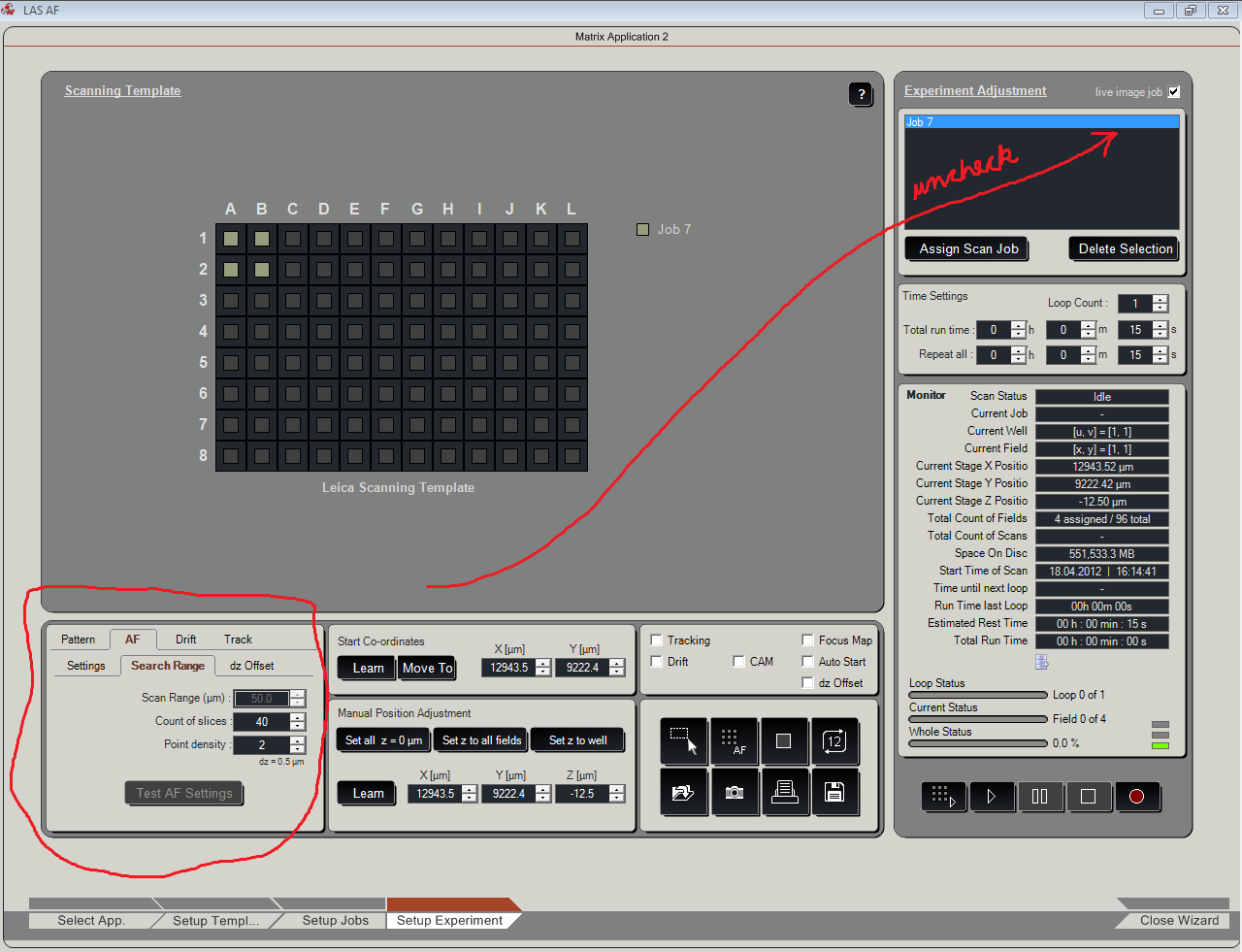
- Select the points where you want to measure auto focus.
- In the top right corner of the UI, . This will activate some auto focus controls.
- . This will display all the fields where auto focus will be measured.
- In "Pattern" tab, select a pattern. For example with the middle pattern, auto focus will be measured in one point in each well.
- In "AF" -> "Search Range" tab, modify "Point density" and observe how the auto focus point pattern changes.
- Define the auto focus stack.
- Select "Search Range" tab.
- Enter the auto focus stack parameters you tested previously.
- Click "Test AF Settings".
- Save the scanning template. and to the template.
The experiment is now ready to be run. First run the auto focus job by ("Start the measurement of the Autofocus Map"). You will see how it progresses from well to well. If the plate is very uneven and there are big differences in z-levels between wells, you may need to increase auto focus scan range, to make sure that the correct focus is found in each well. To visualize the focus map that was created for the plate, .
To run the imaging job, click the "" icon. If all goes well, you will now get in-focus images from all wells.
How to collect stacks
All the steps above apply also for stacks, with the exception that in "Setup Jobs", you must now define the stack dimensions. The stack will be collect either around or starting from the auto focus level, depending on whether you select "Symmetric" or "Asymmetric" as the "Stack to focus point relation" in Configuration.
How to make a sequential scan
All the steps above apply also for sequential jobs. You just need to to create the sequential scan and assign it to the wells.
- Click "Setup jobs".
- Select the current imaging job.
- Click "Ins" -> "New Sequential Job".
- Check that the auto focus job was not lost.
- Click "Setup Experiment" -> "AF" -> "Settings".
- Check that the auto focus job did not disappear from the drop-down menu.
- If it did disappear, you have a problem, it is better to close the wizard and repeat everything and hope for the best.
- Once you have the auto focus job in the menu, return to "Setup Jobs".
- Define the sequential job, channels, stack etc.
- Click "Setup Experiment"
- If you have another imaging job assigned to the wells you want to image sequentially, select them and click "Delete Selection".
- Assign the sequential job to the wells.
- Select the wells again.
- Select the sequential job in the list in top right corner.
- Click "Assign Scan Job".
Using an existing Matrix Screener template
Once you have managed to create and save a scanning template that works, you can use it for your subsequent data collection sessions.
- Set up LAS AF and microscope, and start MatrixScreener as described above.
- "In Select App.", click "".
- Click the icon, .
- Set galvo-stage z-position to 0.
- Go to the microscope and check that:
- Objective Z-level did not change (sample is still in focus).
- The start coordinates stored in the template are ok for this plate (the field of view is within the well).
- If necessary, move stage to a better starting position, and in "Start Co-ordinates", . This will make the current stage position the starting point of the set up.
- Go to Setup Jobs, .
- Go to Setup Experiment.
- Click AF, see Settings. If you , you have a problem.
- Go back to Setup Jobs and see if you .
- If not, restart Matrix Wizard and go to the beginning.
- It may be that saving the auto focus and scanning jobs in Setup Jobs will prevent this problem.